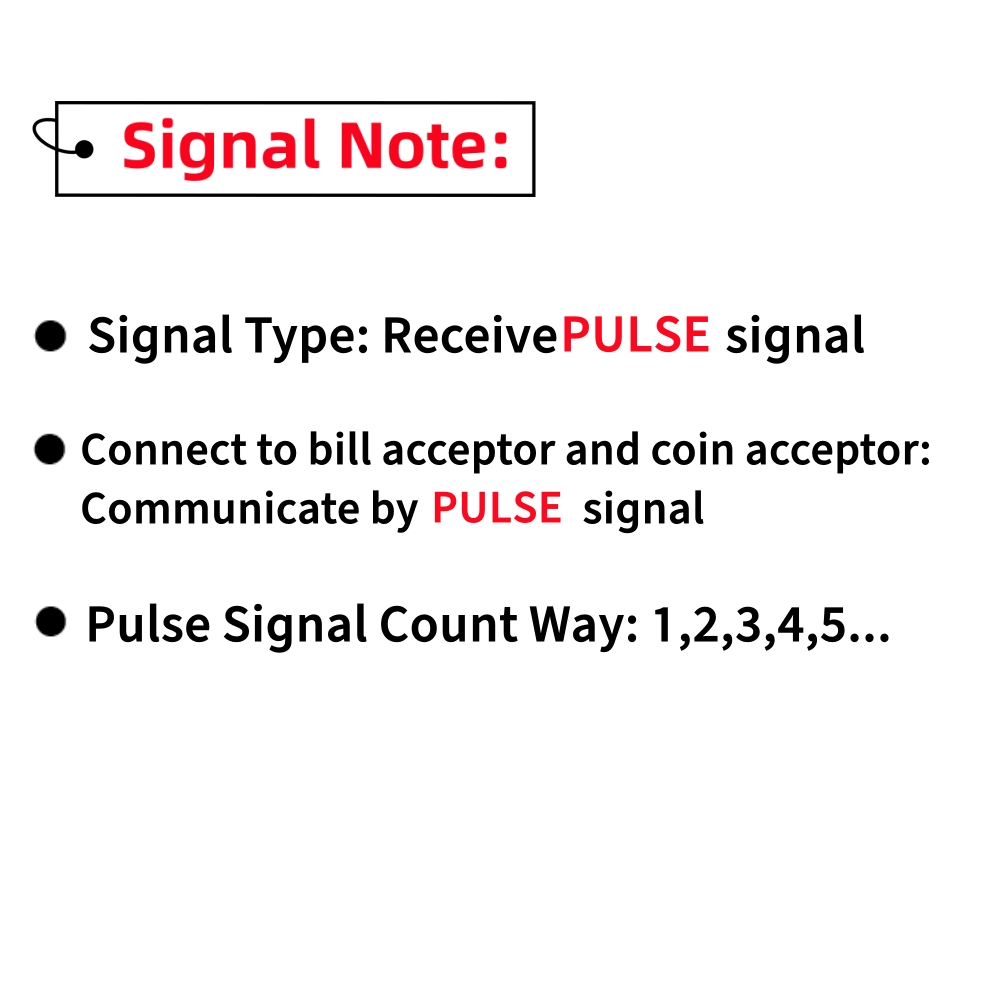


Manual
PAGE-1
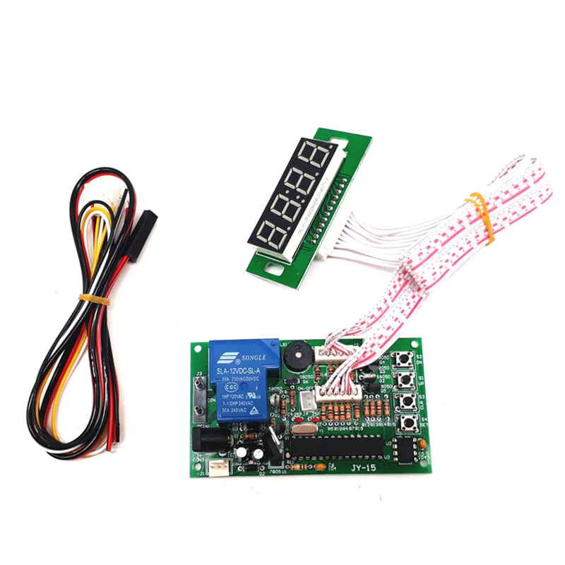
Description
Input Voltage | DC+12V |
Standby | Display shows:00:00, rely: Normal Open (NO) |
Accumulated time | Yes, add time if receive signals again when time is running |
Max current load | 15A |
How it works | |
Mode 1 | Time runs down after receive signals-> Display shows remaining time and supply power to device-> it cuts off power after time runs out |
Mode 2 (Connect a button) | Display shows remaining time after receive signals-> push button start-> time runs down and supply power to device-> it cuts off power after time runs out |
Pause (connect a button) | Push button pause: it cuts off power when pause, display shows remaining time. Re-supply power after push button pause again |
Operating Mode | Please reference to page 2 |
Connection Example | Please reference to page 2 |
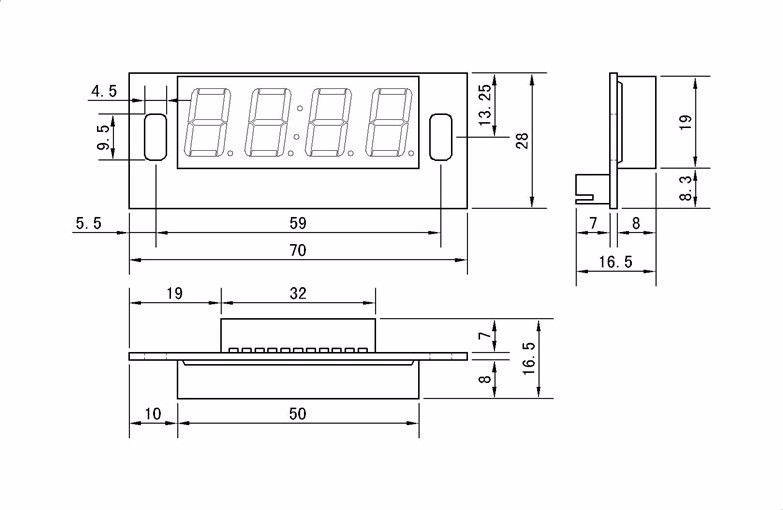
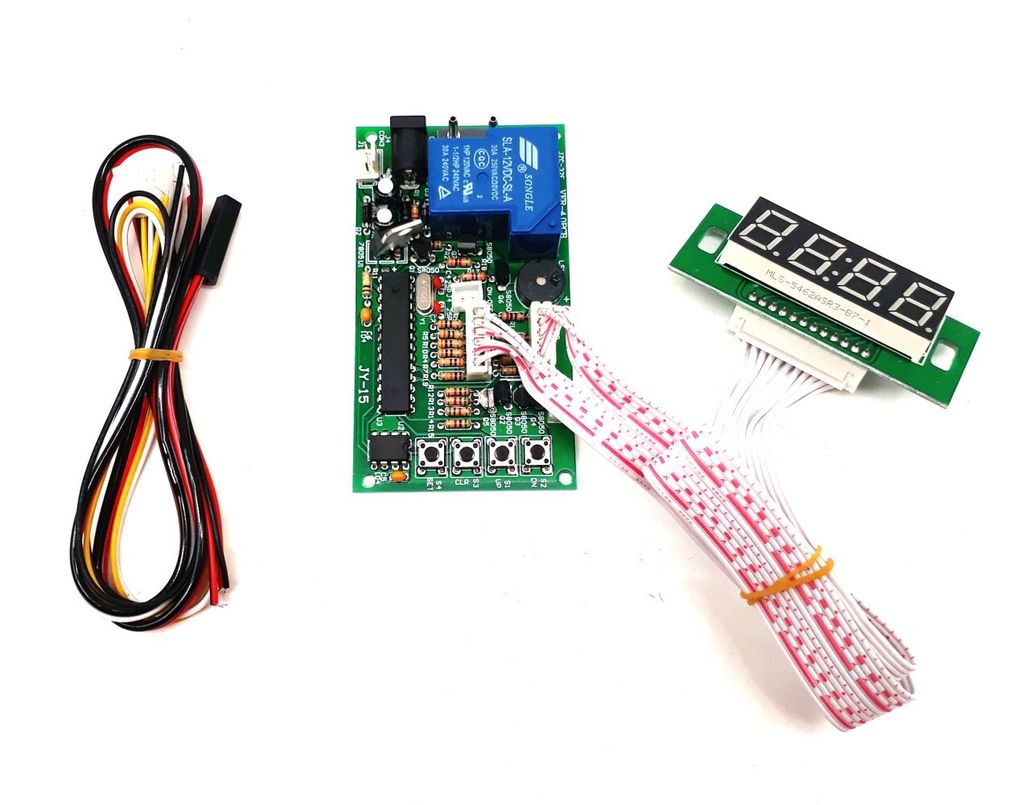
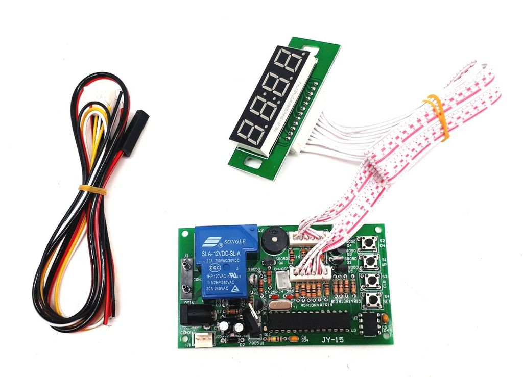
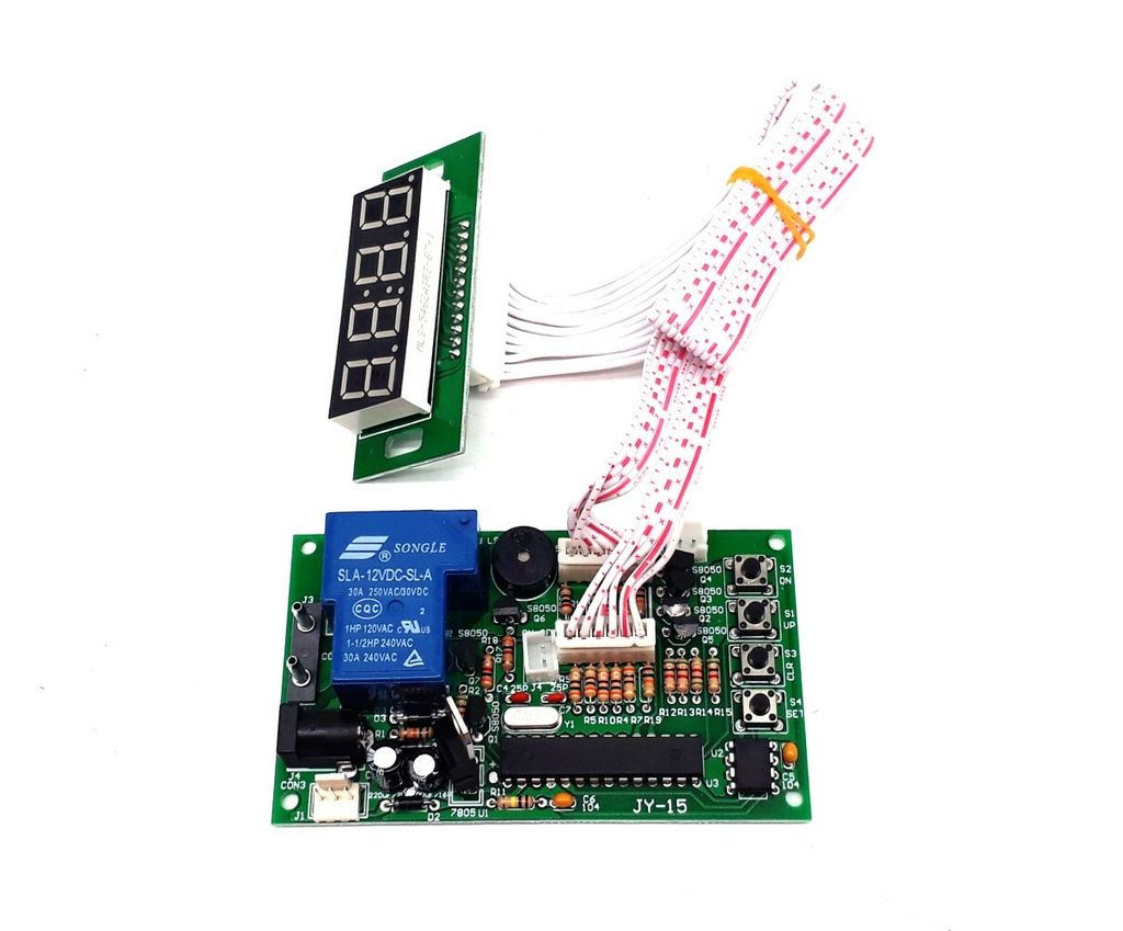
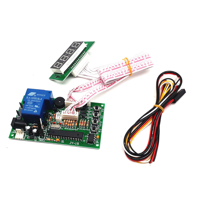
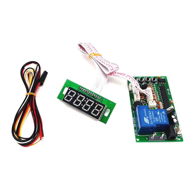
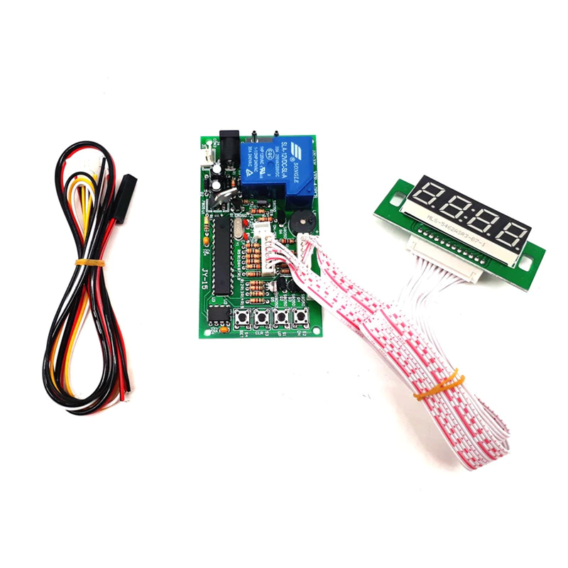
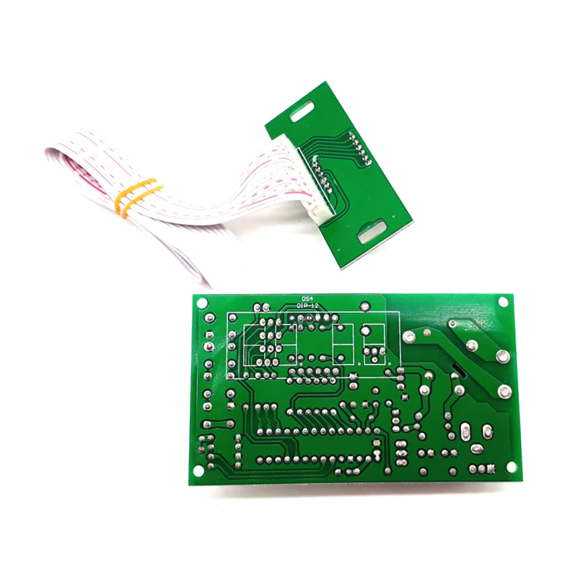
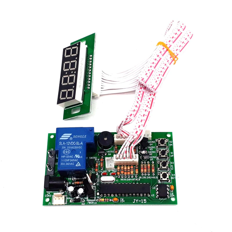
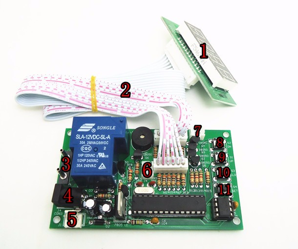
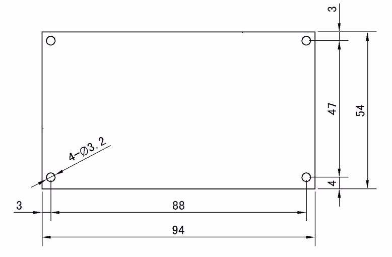
Connection and Position
|
|
Setting
Please follow CODE ON DISPLAY and use button "S1" and "S2" to set up number
INPUT SIGNAL QUANTITY AND TIME
Please press button "S4". “B” flashes. Please set up INPUT SIGNAL QUANTITY to active device (01-50).
Please press button "S4", “A” flashes. Please set up TIME (01-99).
Please press button "S4", “B” flashes. Please set up TIME (01-99).
Please press button “S4” 4 TIMES.
Please set up TIME for Warning Sound.
Please press button "S4" to finish.
PAGE-2
GIVEN TIME: Add time by free if input signals reach SETTING RATE during time is running.
Example Setting: input signal to active device: 01, input signals for given time: 03 give time: 02:10
Add time “02:10” free if receive “3 signals” during time is running.
Please press button "S4" 4 TIMES. “B” flashes. Please set up RATE OF INPUT SIGNAL QUANTITY.
Please press button "S4", “A” flashes. Please set up GIVEN TIME.
Please press button "S4", “B” flashes. Please set up GIVEN TIME.
Please press button "S4" to finish.
Mode Setting
Please follow table to set up operating function:
Please hold on button "S1" and "S2" simultaneously for 3 seconds to get into MODE SETTING.
Please use button "S1" and button "S2" to set up number for CODE
Please press button "S4" to switch to next code
Function | Code on Display | Description | |
A | B | ||
Running Time | 01 | 01 | Time runs down without pressing button |
02 | Time runs down by pressing button | ||
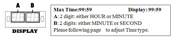
Time Type | 02 | 03 | MINUTE: SECOND |
04 | HOUR: MINUTE | ||
Memory | 03 | 05 | Yes: Remaining time keep running after power off and on |
06 | No: Standby power off and on | ||
Back to standby | 04 | 1-30 | user has no action after push buttons or receive signals in setting time |
Default: 01-03: Bold and base line. 04: not use the function. | |||
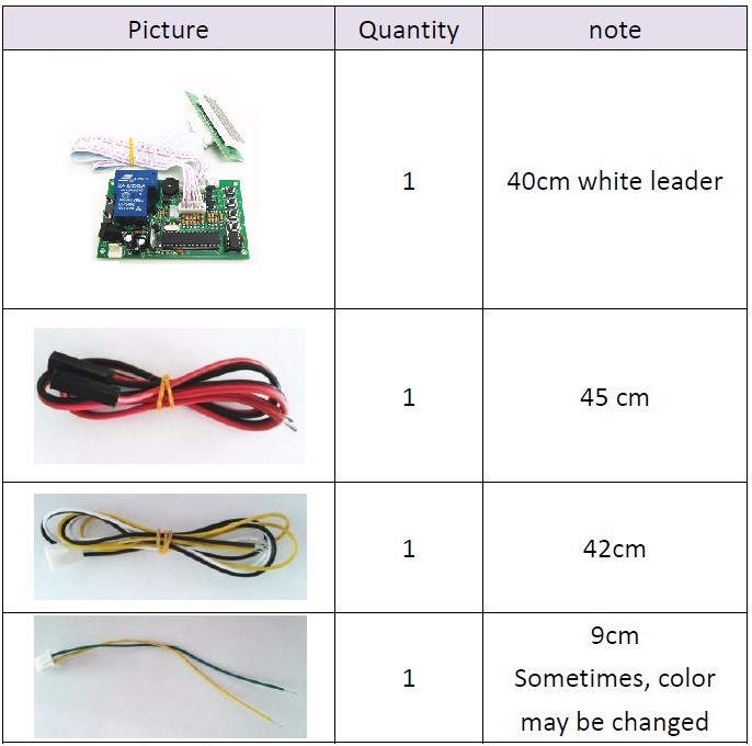
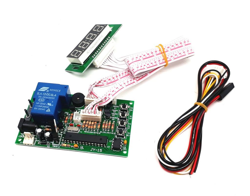
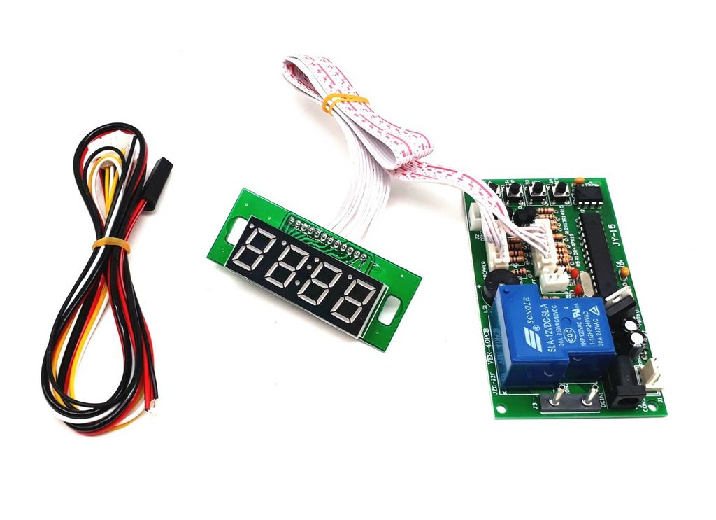
Connection Example
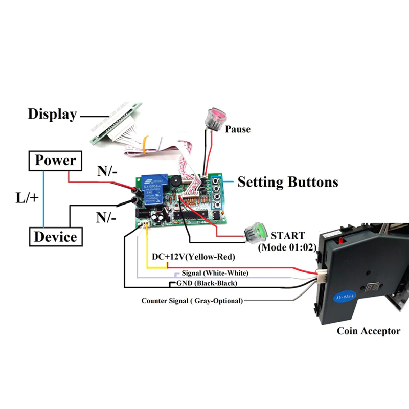

Main board
Display