Description
Input Voltage: DC+12V
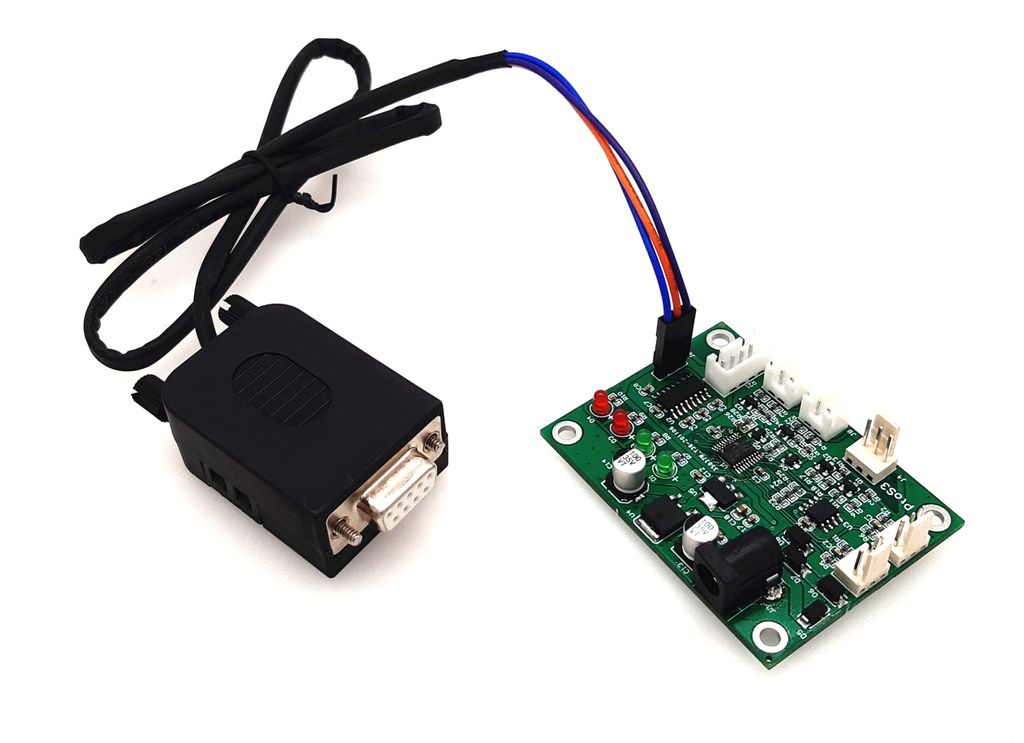
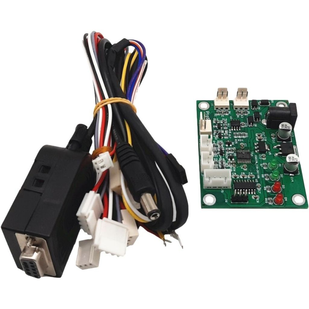
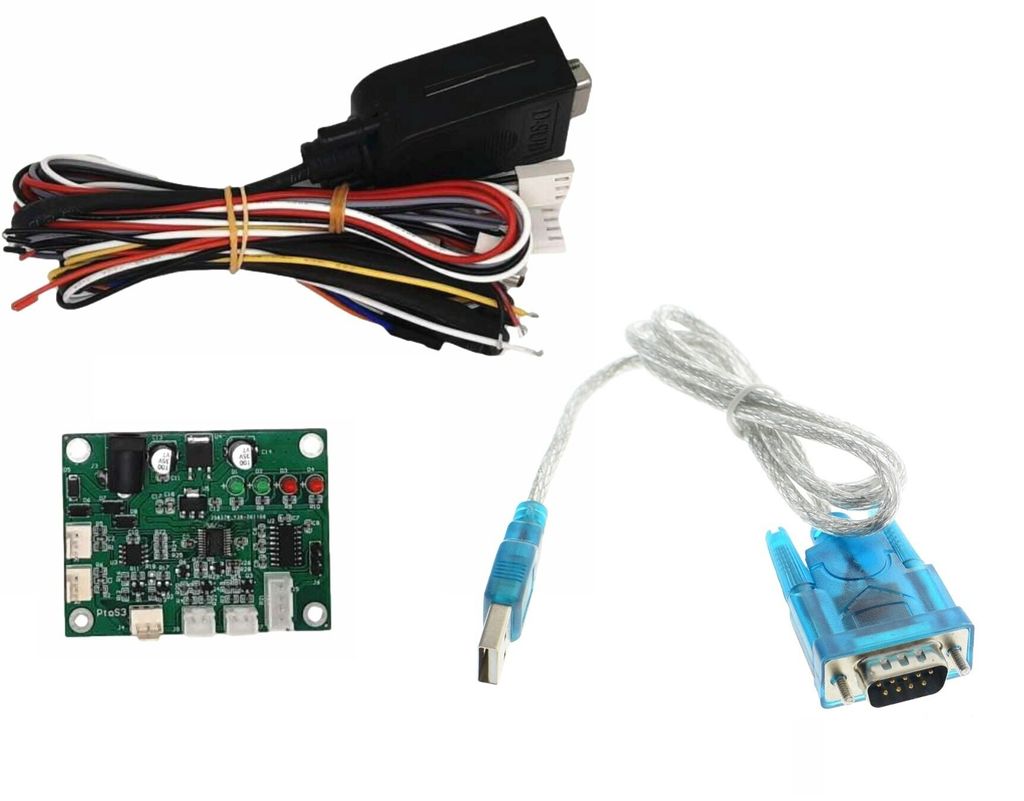
Converter signal Pulse to RS232
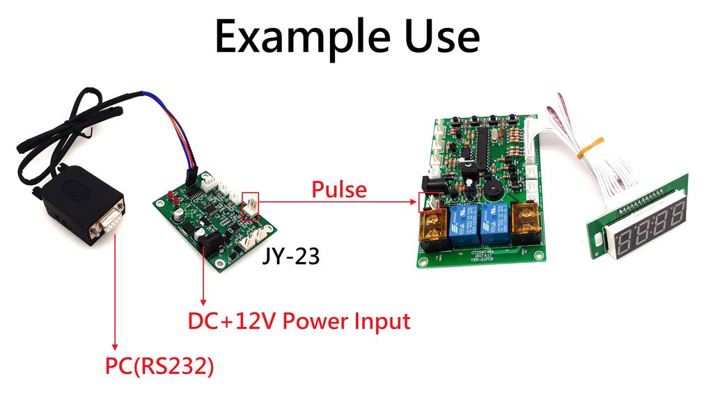
Connect coin acceptor to PC
Send RS232 order to send a pulse siganl or output DC+5V
Usage:

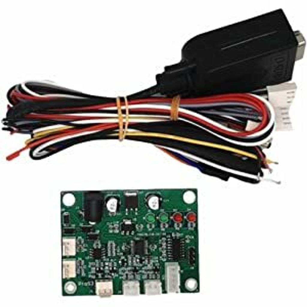
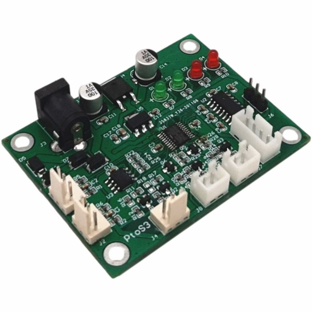
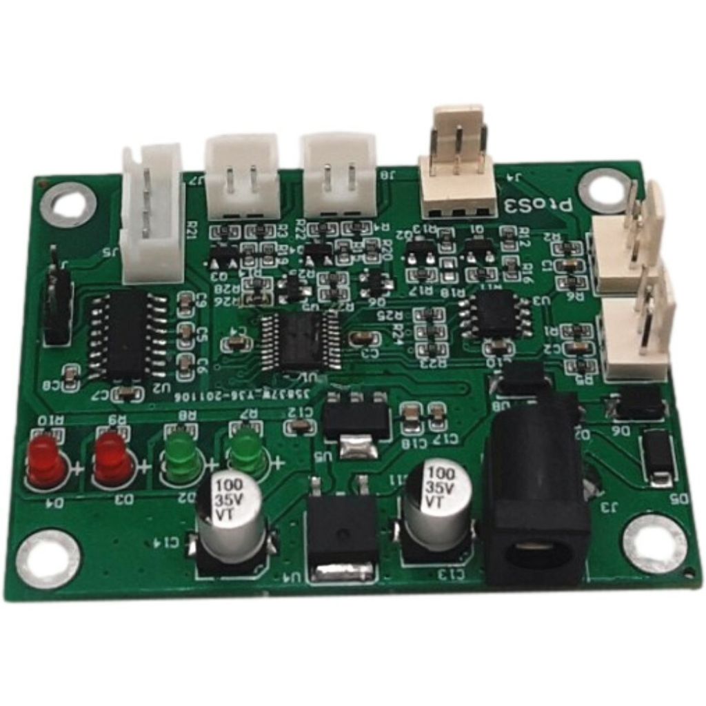
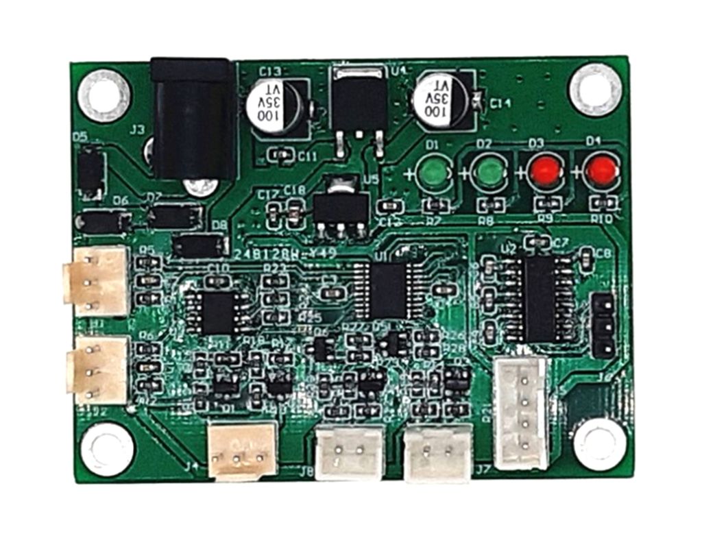
Control board Introduction
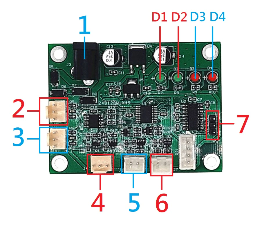
1: DC 12V 5.5*2.1mm
2: Pulse input 1: Channel 1
3: Pulse input 2: Channel 2
4: output 1 pulse when receive order
5/6: output/no output 5V when receiver order
7: RS232 connector
D1: light when staying power on
D2: flash when sending 1 pulse
D3: light when 5&6 outputing 5V
D4: light after receive first order.
Connector Define

Connection Example
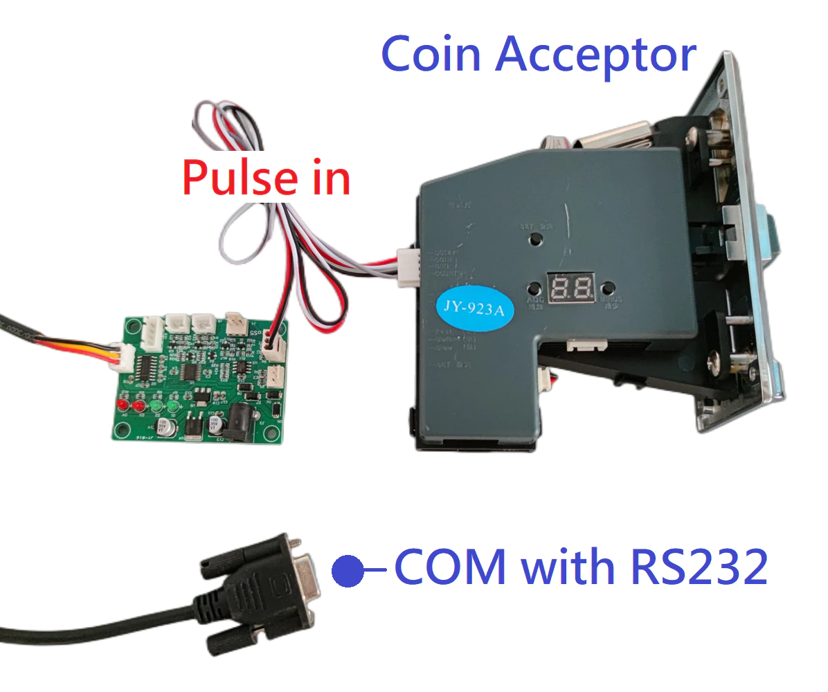

RS232 Protocol
Specification:
(9600,N,8,1) Power consumption: 50MA
Baud rate: 9600 Send Display: Char Format
Parity Bit: NONE Receive Display: Hex Format
Data Bit: 8
Stop Bit: 1Construction:
Head (1) + Len (1) + Data (LEN) + XOR (1) + TAIL (1)
Head (1): 0xF2
Len (1): Data Length
Data (Len): Length is based on Len (1)
Xor (1): From Len (1) to Data (Len)
Tail (1): 0xF3Send data when receive pulse in 100MS
Len (1): 03
Data: Channel (1) +Pn_LL(1) +Pn_HH(1)
Note: Low position first then high position.
Data = CMD (1) + Result (1)
CMD (1): Respond “order byte”, 1 byte
Result (1): Respond order result. 0x00 indicates success.
If value is not 0x00, it indicates fail.Order Detail
No. | Action | Receive |
1 | “5&6”: Output/ no output 5V | F2 01 30 31 F3 |
Success Respond: F2 02 30 00 32 F3 | ||
2 | “4”: output 1 pulse | F2 01 31 30 F3 |
Success Respond: F2 02 31 00 33 F3 | ||
3 | Check total income (Channel 1+2) | F2 01 32 33 F3 |
Success Respond: 32(1)+count 1 (4)+count 2(4) | ||
4 | Reset inbuilt counter | F2 01 35 34 F3 |
Success Respond: F2 02 35 00 37 F3 | ||
------------------------------------Page 2--------------------------------------------
Video for Coin Acceptor
